Raspberry Pi add-on board prototypes
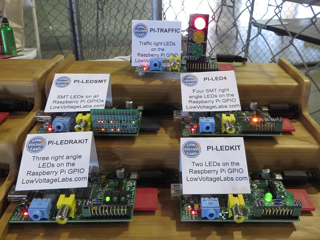
For the 2014 Bay Area Maker Faire I decided to display the Raspberry Pi add-on prototypes we currently have in development. We created a display for Maker Faire with the prototype cards running to get people’s feedback and help us decide what projects to put into production. The goals for these add-on cards are to be small, educational and inexpensive. These add-on cards will retail for prices ranging from $8 to $15.
We got great feedback at Maker Faire and plan to put a couple of the projects into production. But we would like to get even more feedback, so have a look at the projects below and let us know what you think of them. Which ones you like, which ones should go into production and if there is anything you would change.
PI-Traffic
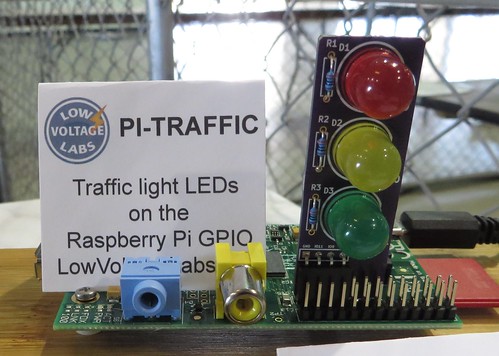
The Pi Traffic light is a vertical add-on card for the Raspberry Pi with three 10mm LEDs connected to the GPIO header. This add-on card could be sold as a kit or fully assembled. The LEDs are connected to GPIO pins GPIO9, GPIO10 and GPIO11.
PI-LEDSMT
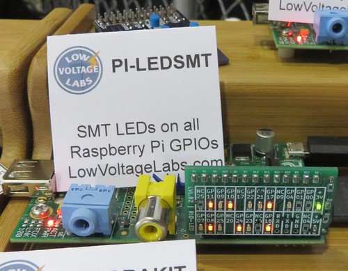
The PI-LEDSMT is a vertical add-on card for the Raspberry Pi that has LEDs on all of the GPIO pins of the GPIO header. This add-on card would be sold fully assembled. Using this add-on card allows the user to see all the activity on the GPIO pins.
PI-LED4
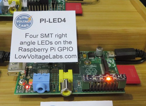
The PI-LED4 is an add-on card for the Raspberry Pi with four right angle surface mount LEDs connected to the GPIO pins on a horizontal PCB that fits over the GPIO header. This add-on card would be sold fully assembled. The four right angle surface mount LEDs are connected to GPIO pins GPIO02, GPIO07, GPIO08 and GPIO11.
PI-LEDRAKIT
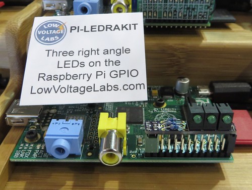
The PI-LEDRAKIT is an add-on card for the Raspberry Pi with three right angle through hole LEDs connected to the GPIO pins on a horizontal PCB that fits over the GPIO header. This add-on card uses all through hole parts and would be sold as a kit. The three right angle LEDs are connected to GPIO pins GPIO07, GPIO08 and GPIO11.
PI-LEDKIT
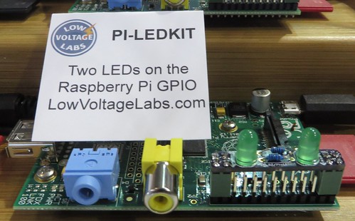
The PI-LEDKIT is an add-on card for the Raspberry Pi with two through hole LEDs connected to the GPIO pins on a horizontal PCB that fits over the GPIO header. This add-on card uses all through hole parts and would be sold as a kit. The two 5mm LEDs are connected to GPIO pins GPIO07 and GPIO08.
PI-BUTTON5
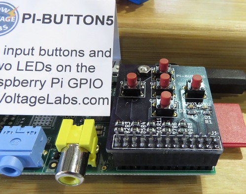
The PI-BUTTON5 is an add-on card for the Raspberry Pi with five input buttons and two output LEDs connected to the GPIO header. This add-on card would be sold fully assembled. The five input buttons are connected to GPIO07, GPIO08, GPIO09, GPIO10 and GPIO11. The two LEDs are connected to GPIO02 and GPIO03.
PI-IRKIT
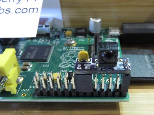
The PI-IRKIT is an add-on card for the Raspberry Pi with an IR receiver IC to enable the use of standard infrared remotes with the Raspberry Pi. This add-on card uses all through hole parts and would be sold as a kit and fits over just half the GPIO header pins. The IR receiver is connected to GPIO18 of the Raspberry Pi GPIO header.
PI-IRSMT
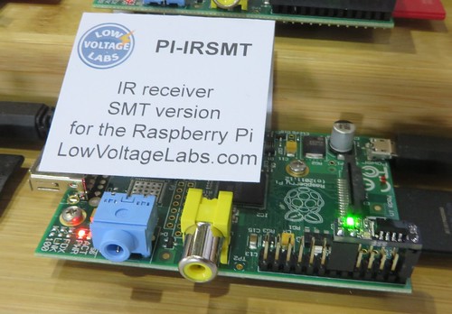
The PI-IRSMT is an add-on card for the Raspberry Pi with an IR receiver IC to enable the use of standard infrared remotes with the Raspberry Pi. This add-on card would be sold fully assembled and fits over just half the GPIO header pins. A surface mount LED is included on the card that flashes when there is activity on the IR input. The IR receiver is connected to GPIO18 of the Raspberry Pi GPIO header.
Please leave a comment below or send a tweet to @LowVoltageLabs.
Pumpkin PCB files in KiCAD format
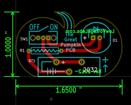
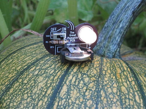
This year at the Seattle and Portland Mini Maker Faires I did a presentation on getting started with designing your own PCB using KiCAD. In this presentation as an example I created a pumpkin shaped PCB with a candle like flickering LED.
Here are the KiCAD schematic and PCB layout files to use as the starting point for your own project:
KiCAD schematic and PCB files (zip file)
These files are released under the Creative Commons Attribution-ShareAlike 3.0 Unported License.
You can see photos of the actual PCB on Flickr:
Great Pumpkin PCB photos
The Pumpkin PCB is now also available as a kit:
Low Voltage Labs Pumpkin PCB kit
VideoOverlayShield is now Creative Commons Attribution-ShareAlike
We’ve decide to update the license on the VideoOverlayShield product. Previously it was licensed under the Creative Commons Attribution-Noncommercial-Share Alike, which says you can copy and remix the product but not for commercial purposes.
We have decided that this is no longer necessary and have changed the license of the VideoOverlayShield to the Creative Commons Attribution-ShareAlike 3.0 Unported License. This allows the copy and remix of the product even for commercial purposes. This also puts the product more in line with the values of the Open Source Hardware (OSHW) Definition.
Arduino shield board outline in gEDA format
I have been working on a few different shield boards for the Arduino platform. In an attempt to make life easier for myself I created a couple starter files for my future projects. The zip file below includes a schematic and PCB file in gEDA format. The board has the four headers and mounting holes for an Arduino shield board. I’ve decided to release the files into the wild for anyone to use.
Arduino shield outline schematic and layout files in gEDA format (zip file)
These files are released under the Creative Commons Attribution 3.0 Unported license.
Looking for open source hardware project ideas
Low Voltage Labs will soon be releasing it’s first open source design hardware project, the VideoOverlayShield for the Arduino platform.
Low Voltage Labs is looking for open source hardware project ideas and would like your input. Do you have an idea for an Arduino shield board or an electronics project that could be used in the classroom? Send us your ideas at the contact page or leave a comment below.
Be sure to check back and see what projects Low Voltage Labs creates next.
